Senin, 23 Februari 2009

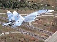
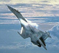
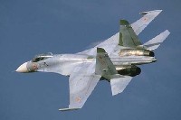
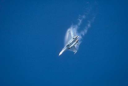
Su-27 Flanker

Introduction

The Su-27 was designed by Sukhoi OKB as a heavy fighter for the Soviet Air Force (Voenno-Vozdushmiy Sily - VVS) and National (Homeland) Air Defense Forces (Protivo-Vozdushnoi Oborony - PVO) to regain air superiority over the F-15 Eagle operated by the US Air Force. In fact, the requirements were based on the performance of the F-15 adding ten percent. The Sukhoi design fulfilled the requirements and beyond. The Su-27 is often proclaimed the best and most successful Russian fighter of the Cold War era.
After the end of the Cold War and USSR, the Sukhoi OKB (often in cooperation with the KnAAPO plant) developed various advanced variants aimed at prospective foreign customers. The aircraft were marketed at international air shows, putting up superb aerobatic displays. The aircraft performance both on paper as in aerobatic displays has stunned many enthusiasts and experts alike all over the world. Also, the Flanker has proven its air superiority in combat during several African wars. The Su-27 and its derivatives are today some of the most popular fighters to be discussed by both aviation enthusiasts and experts.

Design

The main feature for the success of the Su-27 design is its aerodynamic configuration, known as 'integrated aerodynamic concept' by its designers. This configuration is one with extremely blended wing and fuselage. The low-aspect ratio trapezoidal midwing is fitted with large leading-edge root extensions (LERX) and blending into the fuselage creating a single lifting body.
The aircraft has a near-zero static stability and thus require a fly-by-wire system. The SDU-10 pitch-only fly-by-wire system controls the pitch of the aircraft to ensure stability and controllability for the pilot, increase aerodynamic performance, limit overload and angle of attack when needed and decrease the airframe aerodynamic load.
Two AL-31F afterburning turbofans are placed in seperate, widely spaced engine nacelles that are mounted under the lifting body. The air intakes are fitted with variable ramps.
The Su-27 has twin vertical fins fitted on the outer sides of the fuselage and twin central fins underneath. The airbrake is placed in the center of the mid-section of the aircraft behind the cockpit. The tricycle landing gear of Su-27 and Su-27UB has a single wheel on each strut. The nose wheel is fitted with a mudguard to protect against foreign object damage (FOD).

Systems & Avionics

The basic Su-27 is fitted with the SUV-27 fire control system, which incorporates the RLPK-27 radar sighting system, OEPS-27 electro-optical sighting system, SEI-31 integrated indication system, IFF interrogator and built-in test system. The fire control system in integrated with the PNK-10 flight navigation system, radio command link, IFF system, data transmission equipment and EW self-defence system.
The RLPK-27 system and is controlled by the Ts-100 digital computer and includes the N001 pulse-Doppler lookdown-capable radar with a range of 80-100 km in the front hemisphere and 30-40 km in the rear hemispehere for a fighter-sized target. It can simultaneously track up to ten aerial targets in track-while-scan mode and provide interception of the top priority target.
The OEPS-27 electro-optical sighting system consist of the OLS-27 infrared/laser search-and-track system (IRST) and the Shchel-3UM helmet-mounted target designator and is controlled by the Ts-100 digital computer. The OLS-27 sensor is placed forward of the cockpit canopy in the centre. The system acquires and tracks aerial targets by their thermal signatures. The helmet-mounted sight and the laser range finder of the IRST can also be used to visually acquire and determine coordinates of air and surface targets.
The SEI-31 integrated indication system provides flight, navigation and sighting data on the ILS-31 head-up display (HUD) and CRT. The EW self-defence systems provides warning to the crew when illuminated by enemy radar and employs both passive and active countermeasures. The aircraft is equipped with the SPO-15 Beryoza RWR and APP-50 IR decoy dispenser. Chaff dispensers are placed in the tail section between the engine nozels. In addition, the aircraft can carry the Sorbtsiya active ECM pods on its wingtips.

Cockpit

The cockpit is fitted with the K-36DM Series 2 ejection seat. The seat-back is being inclined at an angle of 17 degrees. In the two-seat Su-27UB version, the seats are placed in tandem with the rear-seat being elevated to ensure good forward vision. The basic Su-27 cockpit layout consist of analogue instruments, HUD and CRT display to display data from radar and electro-optical sight (IRST). On both sides of the HUD control panel, there are sensors for the helmet-mounted target designator system. On the right side below the CRT display the RWR indicator is placed.

Weapons

The Su-27 is fitted with one GSh-301 automatic single-barrel 30mm cannon fitted inside the starboard wing LERX. It can be armed with up to 150 high explosive incendiary or armour piercing tracer rounds.
The basic Su-27's primary armament consists up to six R-27R/ER semi-active radar homer or R-27T/ET heatseeking homer medium range air-to-air missiles, as well as four R-73 IR agile all-aspect short range air-to-air missile. The basic Su-27 has only a limited air-to-surface capability consisting of only unguided bombs and rockets.

Upgrading the Russian Air Force Su-27 fleet

The Russian Air Force received its first batch of upgraded Su-27s in 2006. The air force seems to have settled for the mid-life upgrade offered by KnAAPO based on the Su-30MK2, which brings the aircraft up to Su-27SM standard. The Su-27SM is equipped with an upgraded fire control system including the improved N001V radar with phased array antenna, which offers improved performance and air-to-surface mode. The new system enables the use of the RVV-AE (R-77) medium range air-to-air missile and a wide selection of guided air-to-surface bombs and missiles. Another heavily updated feature is the cockpit, which is upgraded with three MFD, new HUD, satellite receiver and new communications set. The aircraft's self-defense suite has also been upgraded.
The Russian Air Force plans to upgrade its entire fleet to Su-27SM standard, but the exact number of aircraft involved remains unclear.

The Su-27SM is based on earlier proposed upgrades for the Su-27SK export version. The Su-27SMK as it is designated has seen two attempts, with at the basis a different radar system (N001M and N001VEP respectively). China was seen as the premier customer for an upgrade package. However China opted to expand its Flanker fleet with multi-role Su-30MKK and Su-30MKK2 instead of upgrading its Su-27SK and J-11 single-seaters. Instead China planned an indigenous upgrade for its J-11s. Other clients also preferred two-seat Su-30MK/MK2. From 2002 onwards, Sukhoi and KnAAPO developed a new deeply modernized single-seat Su-27 derivative known as Su-27BM. Designated Su-35, it will be offered for new export orders, replacing the previously offered Su-35, which was based on the Su-27 and offered in the 1990s.

Based on the Su-35(Su-27BM), the Su-27SM2 upgrade is on offer to the Russian Air Force for the second phase of its Su-27 mid-life upgrade program. The Su-27SM2 upgrade will give Russia's existing Su-27s a similar avionics and weapons suite as offered on the Su-35(Su-27BM). The Russian Air Force has expressed interest in the Su-35, but it remains to be seen whether this will include new air frames or be limited to the Su-27SM2 upgrade.

Upgraded Su-27 Flankers for the Russian Air Force are also planned to be fitted with upgraded engines. Both MMPP Salyut and NPO Saturn have developed modernized and more powerful AL-31F variants. In December 2006, the MMPP Salyut's AL-31F-M1 turbofan passed state acceptance tests for use on the Su-27SM. The AL-31F-M1 produces 132.4 kN (29,765 lb) of thrust in an additional mode, 9.8 kN (2,203 lb) more than the standard AL-31F turbofan. It will be followed by the AL-31F-M2 and the even more powerful AL-31F-M3 with 147.1 kN (33,069 lb) of thrust is also under development to compete for the first stage of the PAK-FA program, Russia's future fifth generation fighter. Rival NPO Saturn meanwhile developed the izdelye 117S, another AL-31F derivative based on the AL-41F which produces 142.2 kN maximum thrust. Co-funded by Sukhoi and UMPO, the 117S will enter series production both at Saturn and UMPO to power the Su-35 export fighters. On Febuary 19, 2008, the firstSu-35 prototype made its maiden flight powered by two 117S. NPO Saturn is also competing to power the PAK-FA with a further modified 117S. Pending a decision on the powerplant selection for the 'first stage' of the PAK-FA program, it remains to be seen which of the options will power the Su-27SM/SM2 upgrades.

The two-seat aircraft will most likely be upgraded to Su-27UBM. Although IAPO offered such an upgrade demonstrated on the Su-30KN, it remains unclear whether the Russian Air Force has opted for this upgrade or plans to have KnAAPO update the two-seaters under a similar program as the Su-27SM/SM2.


Su-27 Flanker


Su-27 Flanker Specifications
Primary Function: Air superiority fighter
Contractor: Sukhoi
Crew: One
Unit Cost: N/A
Powerplant

Two NPO Saturn AL-31F turbofans each rated at 17,857 lb (79.43 kN) dry thrust and 27,557 lb st (122.58 kN) with afterburning
Dimensions
Length: 71 ft, 11.5 in (21.935 m)
Wingspan: 48 ft, 2.75 in (14.7 m)
Height: 19 ft, 5.5 in (5.932 m)
Weights
Empty: 39,021 lb (17700 kg)
Maximum Takeoff: 66,138 lb (30000 kg) -- Flanker-B
Performance
Speed: Mach 2.35 (1,553 mph; 2500 km/h)
Ceiling: 59,055ft (18,000m)
Range: N/A
Rate of Turn: 22.5° / sec Sustained
28.5° / sec Instant


Su-27 Flanker Achievements
  • The Su-27 is one of the most imposing fighters ever built.


Su-27 Flanker Photos
Su-27 FlankerSu-27 Flanker


Su-27 Flanker Family Armament

Aircraft with 10 hardpoints (Su-27, Su-27UB, Su-27SK, Su-27UBK, Su-30KI)


8

6

4

10

1,2

9

3

5

7

Internal:
GSh-301 (150 rounds)

Guided A-A:
R-73
R-27ER
R-27ET
RVV-AE

1X

1X

1X
1X
1X
1X


1X

1X


2X

2X


1X

1X

1X
1X
1X
1X

1X

1X
Unguided A-S:
FAB-500M62/RBK-500/ZB-500
FAB-250M54
FAB-250M62
OFAB-100-120
B-8MI
B-13L
S-25


1X

1X

2X
6X
3X
6X
2X
2X
2X

1X
5X
2X
6X

2X
7X
6X
12X

1X
5X
2X
6X

1X
6X
3X
6X
2X
2X
2X


1X

1X

Guided A-S:
Kh-29T *
Kh-31P(A)*
Kh-59M*
KAB-500Kr *
KAB-1500Kr *


1X
1X
1X
1X
1X

1X
1X

1X


2X
1X

1X
1X
Tekon
1X

1X
1X
1X
1X
1X


* guided air-to-surface weapons can only be used with upgraded fire control system
** stations 1 and 2 are placed in tandem between engine nacelles
Source: Fomin, A., Su-27 Flanker Story
Copyright © 2008 Niels Hillebrand - MILAVIA.NET


Aircraft with 12 hardpoints (Su-35, Su-30MK, Su-33*)


8

6

4

12

10

1,2

9

11

3

5

7

Internal:
GSh-301 (150 rounds)

Guided A-A:
R-73
R-27ER
R-27ET
RVV-AE

1X

1X

1X
1X
1X
1X


1X

1X


1X

1X


2X

2X


1X

1X


1X

1X

1X
1X
1X
1X

1X

1X
Unguided A-S:
FAB-500M62/RBK-500/ZB-500
FAB-250M54
FAB-250M62
OFAB-100-120
B-8MI
B-13L
S-25


1X

1X

2X
6X
3X
6X
2X
2X
2X

1X

5X
6X

1X
5X
2X
6X

2X
7X
6X
12X

1X
5X
2X
6X

1X

5X
6X

1X
6X
3X
6X
2X
2X
2X


1X

1X

Guided A-S:
Kh-29T *
Kh-31P(A)*
Kh-59M*
KAB-500Kr *
KAB-1500Kr *


1X
1X
1X
1X
1X

1X
1X


1X
1X

1X


2X
1X

1X
1X
Tekon
1X

1X
1X


1X
1X
1X
1X
1X


* guided air-to-surface weapons can be used by Su-33 fighter only with the upgraded fire control system
** stations 1 and 2 are placed in tandem between engine nacelles
Source: Fomin, A., Su-27 Flanker Story
Copyright © 2008 Niels Hillebrand - MILAVIA.NET

Jumat, 13 Februari 2009

Mirage 2000

Mirage 2000 familly

Mirage 2000
© Dassault Aviation – F. Robineau

Introduced in operational service by the French Air Force in 1984, in its air defence variant (Mirage 2000 C and B), the Mirage 2000 is praised by all its operators. The quality and the safety of its flight control system, as well as its ease of maintenance raised it at the top of the world references in this field.

These qualities, associated to an extreme ruggedness led Dassault Aviation and its partners to proceed further with their aircraft weapon system, taking into account the emergence of new operational needs and the availability of new technologies.

In 1986, another version called Mirage 2000 N, came to operational service, to fulfill the nuclear missions. With the version called Mirage 2000 D both two versions answered a specific very low altitude penetration need of the French Air Force. Both featured twin-seat configuration and terrain-following radar.

The export version that followed was mainly based on the single-seat concept of the French Mirage 2000 C version. In order to broaden the operational spectrum of the aircraft, air-to-surface capabilities were added, often specific to customer needs.

Because it offers many advantages in terms of overall ownership costs and performance, the multirole concept has been retained for the evolution of the Mirage 2000 family.

In July 1998, during an international exercise in eastern Europe, several French Mirage 2000 have demonstrated their capability to operate from narrow, lightly prepared roads, without even having to use their braking chute.
Deployed in many operational theatres, the Mirage 2000 has become a world reference in terms of availability, maintenance and evolutivity. Its interoperability with NATO aircraft and its efficiency are combat proven.

Mirage 2000-5 Mk2

Mirage 2000
© Dassault Aviation – F. Robineau
The most advanced version in the Mirage 2000 familly

The Mirage 2000-5 Mk2 is a new-generation advanced multirole combat aircraft, descending from the Mirage 2000 lineage, already proven under operational conditions with the air forces of eight countries.

Operational experience, especially within multinational forces, has shown the need for an increased fuel capacity and firepower. This requirement has been fulfilled with the introduction of the Mirage 2000-5 in operational service in 1997.

As new markets were conquered by the Mirage 2000-5, the users of the earlier versions became interested in the aircraft new capabilities.
New Mirage 2000-5 Mk2 aircraft complete existing fleets, and operational aircraft are modernised to gain the same operational capabilities.

The Mirage 2000-5 Mk2 incorporates new technologies and functionalities often derived from the experience gained in the RAFALE aircraft development.
The Mirage 2000-5 Mk2 is ideally suited to interception and air superiority missions.

The Mirage 2000-5 Mk2 is entirely suited to high-altitude interception operations at high supersonic speeds (Mach 2.2 at 50,000ft) thanks to its aerodynamic qualities and its engine, thus allowing it to counter high-performance hostiles. Thanks to a new external load configuration, with air-to-air missiles fitted on the side fuselage hardpoints, the new aircraft offers a much-enhanced firepower.

With these new characteristics, the Mirage 2000-5 Mk2 offers outstanding multirole capabilities and ranks among the best in its category, as demonstrated by its success on the export market.
The Mirage 2000-9, ordered by the United Arab Emirates, belongs to the family of the new Mirage 2000-5 Mk2, purchased by Greece.

System characteristics

Mirage 2000
© Dassault Aviation – F. Robineau
Characteristics and performance of the system

The Mirage 2000-5 Mk2 is available in single and twin-seater versions. With the exception of the internal guns (ventral pod for the twin-seater), the twin-seater Mirage 2000-5 Mk2 keeps all the operational capabilities of the single-seater, including the Mach 2.2 capability.

The twin-seater, used for pilots' conversion and advanced training, can thus very easily be integrated into a combat deployment, and be operated by one or two crewmembers.
Built around a modular and highly adaptive architecture, the Mirage 2000-5 Mk2 system is based on high performance internal sensors such as:

  • The RDY 2 radar manufactured by the Thales company is a latest-generation look-up / look-down long-range radar. Its ability to switch automatically in the detection, tracking and fire-control modes makes it unrivalled for air-to-air missions. Leading technical characteristics are as follows:
    • In air-defence mission, the RDY 2 multimode radar can simultaneously detect up to 24 targets at all altitudes.
    • It can track up to eight targets simultaneously and track four priority targets automatically in both the vertical and horizontal planes. It can evaluate the effects of beyond-visual-range attacks.
    • In air-to-surface mission, it is capable to identify accurately fixed or mobile targets, and to designate them to the weapons.
    • The RDY 2 radar satisfies the essential requirements of modern aerial combat, including firing against multiple targets. The radar employs three pulse repetition frequencies (PRF), with automatic monitoring frequencies for target detection purposes. The system is effective at all altitudes and ensures early detection, coupled with continuous target tracking of a very high standard.
    • The RDY 2 radar is designed to use capabilities in the areas of reconnaissance based on high-resolution images.
  • A laser gyro, GPS-coupled, inertial system featuring a high level of reliability, accuracy and a short alignment time (on ground alert, as well as in flight).
  • A fully integrated internal countermeasures system capable of detecting, identifying and localising the most dangerous air-to-air and ground-to-air threats with the highest accuracy; this system includes multiple jamming and decoying capabilities. Thanks to interferometric sensors, the localisation accuracy provides the option of designating ground-to-air targets to weapons during a SEAD mission.
  • A multifunction data link system.

To assist the pilot in the management of his mission, and to ease reconfigurations, the "Glass Cockpit" technology has been adapted for the Mirage 2000-5 Mk2.

The instrument panel includes 5 displays, among which 3 are color displays. The central screen is mainly dedicated to the tactical situation display. In between this screen and the Head-Up display, another screen -collimated to infinity - displays the main sensor image (radar or laser designation pod). This unique display layout allows the pilot to shift instantly from head-up flying to internal and external monitoring.

Among the other major evolutions of the Mirage 2000-5 Mk2, one can mention:

  • A modular avionics concept.
  • New larger lateral displays.
  • New back-seat colour display repeater.
  • Helmet-mounted sight.
  • Automatic terrain-following system based on a digital terrain file.
  • Digital map on a head-down display.
  • An aircraft-to-missile datalink with an increased number of channels.
  • A discrete multimode datalink system.
  • The new Damocles laser designation pod featuring:
    • 3-5µm infrared imagery,
    • increased laser range.
  • A Flir imager integrated into the Damocles pylon.
  • On-board oxygen generation system.
  • Combined air-to-air and air-to-ground configurations.
  • New multi-channel recording system.
  • Increased maximum take off weight (17.5 t).
  • Very long range stand-off air-to-ground missiles.
  • The introduction of the IR Mica missile.

Thanks to its modular avionics and to the flexibility of its man-machine interface, the Mirage 2000-5 Mk2 offers its users the highest flexibility and evolution capability.

Operational capabilities

Mirage 2000
© Dassault Aviation – F. Robineau

Thanks to this equipment configuration (which remains open to further evolution), the Mirage 2000-5 Mk2 demonstrates an extended range of operational capabilities.

The weapon system integrated maintenance contributes to the aircraft ease of operation and operational readiness. The principle of self-monitoring, associated to the equipment's high level of reliability, considerably reduces the number of expensive programmed maintenance operations. Thus, we can easily understand the success of distant and long duration Mirage 2000 deployments, in war time (i.e. Kosovo, Afghanistan, …).

The Mirage 2000-5 Mk2 retains the same airframe and engines as the Mirage 2000 and therefore features the same outstanding performance, ruggedness and service-life characteristics. It is characterised by a high mission-readiness, as demonstrated by several real war operation. Its ability to operate autonomously facilitates deployment with a minimum support.

Over 1,000,000 flying hours have been logged. Throughout this experience, it is important to note that, thanks to an exceptional electrical flight control system, not a single aircraft has been destroyed due to a loss of control.

Extended carrying capabilities

Mirage 2000
© Dassault Aviation – F. Robineau

The Mirage 2000-5 Mk2 provides nine hard-points for external stores (five under its belly, four under its wings). These hard-points can be used to attach weapons, pods, launchers, jettisonable external tanks or pylons, or for carrying various combinations of external stores, up to 6.3 metric tons, including 'smart' weapons for a wide variety of operational requirements:

  • The non-French weapons can be integrated more easily.
  • The installation of specialised pods allows using the aircraft for dedicated missions such as electronic reconnaissance or in-flight buddy-buddy refuelling of other aircraft.
  • The underwing store stations are thereby available to carry 1,700 or 2,000 litres fuel drop tanks, providing the aircraft with increased range.
  • In air-to-ground mission, the future French AASM modular weapon will also allow simultaneous firing against multiple targets (even close together).
  • The Scalp/Storm-Shadow missile is a long-range cruise missile with a conventional warhead, best employed for pre-planned strikes against hardened and protected stationary or moving targets. This missile will be used for long-range surgical strikes. It has an all-weather, day/night capability and will be used at low altitudes in order to give the launching aircraft maximum operational flexibility. Fire-and-forget type missile, it readily adapts to firing conditions and involves only a minimal pilot workload -- an invaluable attribute during stressful wartime conditions. This long-range pre-strategic cruise missile is also considered to be an economical weapon for use against heavily defended airfields. An outstanding feature is its ease of deployment from safe stand-off distances.
    The Scalp is fully 'fire and forget', allowing the aircraft to depart from the firing zone immediately after launch. The missile then flies on, at low altitude, until it impacts the target.
  • In air-to-air missions, the Mirage 2000-5 Mk2 derives full advantage from the high firepower conferred by its load of 6 radar-guided and heat-seeking Mica missiles. It can fire 6 missiles simultaneously. An aircraft/missile data link feeds in-flight target designation data updates to the launched missile. If circumstances demand, a Mirage 2000-5 Mk2 pilot can also fire the 6 Mica missiles in the fire-and-forget mode, dispensing with the data link. The BVR and "discrete" MICA IR missile firing capability constitutes a threat that is very difficult to counter, even for the best ECM-protected opponent.
  • The Mica missile can operate at ranges from a few hundred meters to 60 km. It is the only missile in the world capable of performing all air defence missions, from long-range interception to aerial combat and self-protection.
  • The optional helmet-mounted sight, when associated with the IR MICA missile, considerably increases the Mirage 2000-5 Mk2 efficiency in air combat. Like the Magic 2, the MICA IR missile features an autonomous search mode, which is perfectly integrated with the weapon system. In all mission phases, the pilot uses the IR homing heads of these missiles as IRST (Infra-Red Search and Track).

To date, 5 different air forces have chosen the new-generation Mirage 2000-5 under a program involving almost 200 aircraft.
About 600 Mirage 2000 are operational world-wide; they equip eight Air Forces and are considered by several more.

Aircraft characteristics

Mirage 2000
© Dassault Aviation – F. Robineau

Dimensions :

Span..................................................................29.9 ft
Length...............................................................47 ft
Combat weight..................................................21,000 lbs.
Maximum thrust of the SNECMA M53-P2............98 kN
Two versions.....................................................single and twin-seater
Internal weapons (single-seater)......................2 * 30 mm guns
Store stations....................................................9
Maximum take off weight...................................38,500 lbs.
Fixed (removable) probe for in-flight refuelling..Buddy-Buddy capability
Maximum Mach number......................................Mach 2.2+
Approach speed.................................................140 Kts
Maximum climbing speed....................................60,000 ft/min
Authorised minimum speed in flight....................0 Kt
Time to climb to 36,000 ft/Mach1.8.....................5 min
Operational ceiling..............................................55,000 ft
Loiter time at 150 N.M. from the base at Mach 0.8/25,000 ft*: 2hr 40 min
Range / combat at M 0.8/15,000 ft**: 830 N.M.
Turn Around Time (Refuelling and 6 Air to Air reloading): 15 min
* 3 external tanks + 6 MICA.
** 6 Mica, external tanks dropped prior to combat.
Demonstrated availability in war time (Kosovo): 100% Oleh:© Dassault Aviation – F. Robineau


Eurofighter Typhoon

First British Typhoon Block 5 arrives at RAF Coningsby, UK
Eurofighter Typhoon is an agile, highly maneuverable, twin-engine strike fighter, designed primarily for air superiority and air supremacy missions, with secondary attack capability. The aircraft's ability to gain air superiority beyond visual range (BVR) and in close combat, and at the same time deliver high sortie rates against air, naval and ground targets in all weathers with a variety of weapons, demands close attention to pilot workload. In Eurofighter the pilot flies through use of a computerized flight control system, which offers full carefree handling.

The Saudi Typhoon order is now secured. Eurofighter GmbH has signed a contract with its shareholder BAE Systems acting as the industrial prime contractor on this government to government contract for the supply of 72 aircraft to the Kingdom of Saudi Arabia. The contract represents the second and most significant export order for the Typhoon, first was the sale of 15 fighters to Austria. Saudia is expecting the first Typhoons delivered by 2009.

Including the recent order, the Typhoon order book now totals 707 Eurofighter aircraft. The four Partner nations ordered 620 aircrat: 180 for Germany, 121 for Italy, 87 for Spain and 232 for the United Kingdom. Austria placed an order of 15 aircraft, the first two were delivered in July 2007. To date, 137 Series Production Aircraft, including six Instrumented Production Aircraft operated by industry, have been delivered to the customer Nations: 48 Royal Air Force, 37 German Air Force, 26 Italian Air Force, 18 Spanish Air Force and 2 to Austria. Thirty Tranche 2 aircraft are already in final assembly. Avionics and engine testing has already started for Type Acceptance of Block 8, to be achieved in Spring 2008, with deliveries scheduled to begin in Summer next year.

Typhoon to Compete in Norway?

The Royal Norwegian Ministry of Defense has agreed an industrial participation program with Eurofighter GmbH for the future enhancement of the weapon system. With the evolving role of aerial attack in modern combat, Typhoon's strike capability is also being enhanced, with inclusion of relevant weapon systems, sensors, targeting and communications packages as part of the baseline aircraft. An important Typhoon feature is its capability to operate from hastily prepared bases and small runways for worldwide operations. The aircraft is equipped with an advanced multi-mode radar and an extensive range of sensors and electronic countermeasures.

By the end of June 2008, 135 Eurofighter Typhoon have been delivered to seven units in four nations. The nations’ fleets have accumulated over 40,000 flight hours by that date, additon to over 5,600 test flight hours accumulated by the industry fleet. Typhoon units began assuming responsibility for NATO air defence operations in 2007, beginning in Italy and the United Kingdom. Germany has followed since January 2008, commencing Quick Reaction Alert (QRA) operations with Eurofighter Typhoon at Neuburg. Spain is expected to follow soon.

The aircraft is developed and produced by the Eurofigther consortium, which includes Alenia Aeronautica, BAE SYSTEMS, EADS Germany and EADS CASA., of the four partner countries, Italy, United Kingdom, Germany and Spain. 105 production aircraft have been delivered to date including five Instrumented Production Aircraft operated by industry and owned by the NATO Eurofighter and Tornado Management Agency NETMA.

The Typhoon began its air force career as an air superiority fighter, but in recent months it is beginning to unlock its multi-role potential. NATO Eurofighter Tornado Management Agency (NETMA) has committed to the first phase of the Tranche 2 forward development program providing for precision attack capability for the Typhoon, introduction of Paveway IV and Enhanced GBU-16 alongside work to integrate a Laser Designator Pod. Combined with the Type Accepted of the Block 5 aircraft, the enhanced ground equipment for use with the Block 5 standard is now cleared for use, including a more capable version the Ground Support System. Folowing a successful test program seven Typhoons from RAF XI Squadron, based at RAF Coningsby, Lincolnshire participated demonstrated their operational capabilitiesthe at the Green Flag exercise at Nellis AFB in the USA. XI squadron's Typhoons are expected to be declared 'combat ready' by the target date of 1 July 2008. Over the two-week period the Typhoons dropped a total of 67 munitions, comprising 43 Paveway II bombs, eight enhanced Paveway IIIs and 16 1,000 lb (454kg) free fall weapons. Exercise Green Flag West is a joint USAF and Army exercise in which close air support for ground forces is a crucial element aimed at preparing air and ground forces for deployment to overseas operational areas. It is played out in scenarios which simulate the sort of asymmetric combat experienced in conflicts such as those in Iraq and Afghanistan.


Block 5 Capabilities

Block 5 supports full air-to-air and initial air-to-ground capabilities. The aircraft is cleared for the 9g envelope as intended, with additional features such as sensor fusion, the full Direct Voice Input, enhanced GPS, and Defensive Aids Sub-System (DASS) countermeasures including automatic chaff and flare dispensers. The radar air-to-surface modes are enhanced with ground mapping, and the aircraft also provides initial FLIR (Forward Looking Infra-Red) capability. Block 5 Eurofighter Typhoon is cleared to carry AMRAAM, ASRAAM, IRIS-T and AIM-9L air-to-air missiles, as well as Paveway II laser-guided bombs and GBU-16s. External fuel tanks are certified for supersonic flight, while air-to-air refueling is cleared for all customer specified tanker types. The British RAF and Italian Air Force received its first Block 5 aircraft in August 2007.


Tranche 2 Production Phase:

251 of the total 620 production Typhoons will be "Tranche 2" standard. These comprise 236 aircraft for the core nations plus 72 Tranche 2 aircraft ordered by the Kingdom of Saudi Arabia and 15 Tranche 2 replacing Tranche 1 aircraft in the nations that have been delivered to Austria. Early aircraft for the Kingdom of Saudi Arabia will be taken from the UK final assembly line and the RAF will receive this number of diverted aircraft later.

Eurofighter Typhoon aircraft production will soon progress to the next stage, with the first flight of the Tranche 2 Typhoon which took place at EADS Military Air Systems' site in Manching on January 16, 2008, piloted by EADS Test Pilot Chris Worning. The significant Tranche 2 capabilities focus mainly on the new mission computers which deliver the higher processing and memory capacity required for the integration of future weapons such as Meteor, Storm Shadow and Taurus. Differences in the build standard to Tranche 1 are related to changes in production technology or obsolescence.

The first aircraft fitted with full Tranch 2 avionics is Instrumented Production Aircraft Seven (IPA7), is a German single seat variant, representing the full Tranche 2 build standard. The aircraft will be used to test and certify 'Type Acceptance' for Typhoon Block 8 - the first capability standard of Tranche 2, anticipated for April 2008. This work will be carried out together with the BAE Systems-operated IPA6 Tranch 1 Typhoon fitted with Tranche 2 mission computer suite and avionics features. The first series of EJ200 engine flight testing for Tranche 2 was successfully concluded at the end of November with IPA2 in Italy. Deliveries of Tranche 2 Eurofighter Typhoons to all four Partner Nations will begin in Summer 2008 starting with the British RAF. Deliveries are scheduled to run until 2013. At present, 32 aircraft are in final assembly.

Further enhancements are currently considered within the Main Development Contract (MDC), currently in final negotiation, formulating the roadmap for the integration of future capabilities. Another future enhancement will include the fielding of the e-scan AESA radar capability. Recently, the Euroradar consortium conducted the first flights of the CAESAR (Captor Active Electronically Scanning Array Radar) antenna on DA5 at Manching, Germany.

Eurofighter Typhoon: Retrofit and Upgrade Programs

The R2 Retrofit program is intended to bring all the earlier Typhoons up to the Block 5 standard. All 115 Tranche 1 Eurofighter Typhoon aircraft will be standardized through a series of "Capability Upgrade" projects. Aircraft in Blocks 1, 2 and 2B, are now being upgraded to Block 5 capability, also known as Final Operational Capability (FOC), in order to maximize the aircraft capability at the national fleet level. Upgrades will be included in scheduled maintenance activities to enhance overall fleet availability.

The first non-Block 5 aircraft to be brought to FOC standard is BS021, the 21st single seater of UK production. Only a few days later, German aircraft GS019 joined the program. Both are Block 2B aircraft. This functionality standard represents the full air-to-air functionality, whereas Block 5 includes this plus the enhanced carefree handling air-to-ground capability to drop laser guided bombs. As of February 2007, six aircraft are undergoing retrofits (three in Germany, two in the United Kingdom and one in Spain) with a seventh aircraft soon to join the project in the UK.

Priority in the R2 programme is on the upgrade of Block 2B aircraft, as less work is required to bring these aircraft to the higher performance level. By the end of 2007, the combination of Block 5 new aircraft deliveries and upgraded R2 aircraft will enable the Partner Air Forces to meet their NATO commitment goals.

Following on from Block 2B aircraft, Block 2 Eurofighter Typhoons with the initial air-to-air capability will be upgraded. Finally early Block 1 aircraft (all of them twin seaters) will enter the program. All Tranche 1 aircraft are scheduled to complete upgrade to Block 5 FOC standard by early 2012.

Eventually, all Tranche 2 aircraft will also go through the Phase 1 Enhancement program beginning 2011, covering new software architecture, enhanced multirole man-machine interface (MMI), integration of a new targeting pod, enhancements of MIDS (Multifunctional Information and Distribution System) datalink, Global Positioning System (GPS) navigation system, Defensive Aids Sub-System (DASS), communications, improving ‘network centricity’ and expanded weapon support including Paveway IV and Enhanced GBU-16.

A second batch of future enhancements has been submitted during the Berlin Air Show this year. “Phase 2 Enhancement (P2E)” is targeted to be implemented by the end of 2014. It focuses on the introduction of enhanced weapons expected at this time, like enhanced Storm Shadow, Taurus, supersonic delivery of Paveway IV weapons, Brimstone, Small Diameter Bomb, AMRAAM C-5/7, and Meteor. Other improvements of subsystems are also expected, including further enhancement of DASS. Further enhancements are expected for Tranche 3 currently under negotiations with the core customers. The objective is to have a contract ready by end 2008/early 2009.

Note: By mid- 2008 all Block designations have been deleted from the Typhoon program, except for Block 9 which has been instituted as a placeholder for future capabilities, to be more flexible in adapting future customer requirements. Oleh:defense-update.com

Dassault Rafale

Rafale
© Dassault Aviation – F. Robineau

The origins of the RAFALE can be traced to joint discussions between European nations taking place in the early eighties. But in the wake of the tri-national Tornado program which had put the most emphasis on air-to-surface functions, it soon appeared that the prime requirement of participating nations other than France was predominantly on the air-to-air side.

The French Forces wanted a balanced multi-role aircraft that would be able to replace 7 types of aircraft around 2000-2010 :

  1. Jaguar (air-to-ground attack),
  2. Super-Etendard (carrier-based air-to-ground attack),
  3. Crusader (carrier-based air cover of the naval group),
  4. Mirage F1 (multi-role),
  5. Mirage 2000 C (air defence),
  6. Mirage 2000 N and D (precision strike/interdiction with conventional and nuclear weapons),
  7. Mirage 4 (nuclear strike and recce),

Two of the types to be replaced had to be carrier-based with all the resulting implications in terms of force projection capability: fast-deployed, self-supporting and lethal with limited size.

This was the rational that eventually led to the decision by the French industry and Government to go it alone on RAFALE and provide it with distinctive features tuned to world-wide - opposed to strictly West European - market expectations.

Smart and discrete sensors

Rafale
© Dassault Aviation – F. Robineau

The first and most important sensor of RAFALE is obviously its new generation Thales RBE2 radar.

However, in those circumstances when absolute discretion is the most relevant factor, RAFALE can rely on several other sensor systems :

  1. The front-sector optronics (OSF), developed by Thales, is completely integrated within the aircraft and can operate both in the visible and infrared wavelengths.
  2. The SPECTRA electronic warfare system, jointly developed by Thales and MBDA, provides the aircraft with the highest survivability assets against airborne and ground threats.
  3. The real-time data link allowing communication not only with other aircraft, but also with fixed and mobile command and control centres.
  4. For those missions requesting the use of it, RAFALE can also rely on the Damocles optronic/laser designation pod.

Computing power

Rafale
© Dassault Aviation – F. Robineau

The mere addition of these sensors has no exceptional significance, as it has already been implemented on several combat aircraft. What makes the essential difference with RAFALE is the cross fertilization process between all those sensors, the continuous fusion of the data they provide, their analysis and their synthesis allowing to transform the pilot into a true tactical decider, instead of a simple systems operator. It is the essence of the multisensor data fusion concept implemented aboard RAFALE.

The core of the enhanced capabilities of the RAFALE lies in a new Modular Data Processing Unit (MDPU). It is composed of up to 18 flight line-replaceable modules, each with a processing power 50 times higher than that of the 2084 XRI type computer fitted on the early versions of Mirage 2000-5.
The MDPU, which is composed of commercial-off-the-shelf elements, is the cornerstone of the avionics/weapon upgradeability of the RAFALE. Thanks to its modular architecture, the system is highly adaptable, and new avionics and new ordnance now under development can be easily integrated. Enough growth potential has been built into the RAFALE to ensure that the design has warfighting relevance beyond 2030.

Sensor data fusion provides a link between the global battlespace surrounding the aircraft and the pilot's brain with its unique ability to grasp the outcome of tactical situations and make sensible decisions. It hinges on the computing power of the MDPU to process data from the RBE2 ESA radar, the front sector optronic system, the SPECTRA EW system, the IFF and the data-link (L16 or custom).

Advanced weapons

Rafale
© Dassault Aviation – F. Robineau

The RAFALE's mission system has the potential to support all current and planned armaments, namely:

The Mica air-to-air missile, in its MICA IR (heat-seeking ) and EM (active radar homing) versions,

  • The upcoming AASM range of modular air-to-ground weapons,
  • The Scalp/Storm Shadow long-range stand-off missile,
  • The upcoming Meteor long-range air-to-air missile,
  • Anti-ship missiles (Exocet),
  • Laser-guided bombs,
  • Conventional air-to-ground ordnance,
  • Customer-selected weapons.

The RAFALE's stores management system is Mil-Std-1760 compliant, which allows for the integration of customer-selected weapons.

With an empty weight of about 10 tons, the RAFALE is fitted with 14 hard points (13 on the RAFALE M). Five of them are capable of drop tanks and heavy ordnance. Total external load capacity is over 9 tons ( 20,000 lbs.).

Buddy refuelling missions can be carried out into portions of the airspace out of reach of dedicated tanker aircraft.

All versions of RAFALE are fitted with the Giat Industries Defa 791 30-mm cannon, capable of firing 2,500 rounds per minute.

With its high carrying capability and its powerful mission system, RAFALE can combine ground attack and air-to-air combat missions during the same sortie. It is also capable of performing multiple functions at the same time such as beyond visual range (BVR) air-to-air firing during the very-low-altitude penetration phase. This gives RAFALE impressively broad multi-role capabilities, along with a high degree of survivability.

Low operating costs

Rafale
© Dassault Aviation – F. Robineau
Mission-ready with low operating costs

RAFALE supportability and mission readiness capitalise on the undisputed track record of the current generation of French fighters such as the combat-proven Mirage 2000.

From the early beginning of the development phase, French MOD assigned very stringent Integrated Logistic Support requirements on RAFALE programme, well exceeding the prowess of Mirage 2000. Through concurrent engineering and Computer Aided Design (CAD) techniques, the best technological choices were made in order to favour reliability, accessibility and maintainability.

These extensive ILS studies, together with bold technological choices, led to supportability features exceeding the preliminary requirements:

  • Strengthened by more than 20 years experience of integrated testability through Mirage and Atlantic programme, RAFALE features a comprehensive and accurate Integrated Testability covering all aircraft systems and allowing Printed Circuit Boards exchange at flight line: Testability targets call for a 95 percent fault detection, plus the ability to detect all safety-critical failures,
  • Ergonomic (CAD) studies were conducted in order to check for main components accessibility within aircraft bays, ensuring that all flight line operations would be swift and error free, yielding very short repair times,
  • A unique (automatic) centralised weaponry safety system gets rid of all safety pins and end-of-runway actions, and contributes to achieve outstanding Turn Around Time in operation,
  • Advanced manufacturing techniques together with CAD uses eliminate long conventional boresighting operations after gun, HUD or radar exchange.

All these maintainability aspects have been thoroughly assessed and validated by French Navy and French Air force users. RAFALE is already well in service and enjoys from day one a very high availability and sortie rate (close to 300 FH/year/aircraft) in the confined and stringent aircraft carrier environment.

For self-supportability, the RAFALE is designed to require the minimum of ground support equipment: it is equipped with an on-board oxygen generation system, and with a closed-loop cooling fluid system for on-board coolanol and nitrogen circuits. The built-in Auxiliary Power Unit provides electrical power until the engine-driven generators come on line. During exercise "Trident d'Or", French Naval Aviators validated the RAFALE hot refuelling procedure.

Affordable high-tech fighter

A reliable and easily maintainable fighter invariably translates into considerably lower maintenance costs:

  • There is no complete airframe or engine depot level inspection required throughout the aircraft service life, and only specific components such as Shop Replaceable Units (SRUs) are returned for maintenance/repair. The same philosophy applies to the M88 turbofan composed of 21 modules, interchangeable without needing full balancing and re-calibration. For maintenance and repair, only modules or parts are returned to the depot/manufacturer.
  • The decision to eliminate the complex systems from the early design phase (a fixed refuelling probe, but removable, fixed air intake, no airbrake, no constant speed drive due to variable frequency,...) ensures spare, maintenance man hours and support equipment reduction. Also, the full interchangeability between elements due to the mastering of manufacturing techniques (no need of fitting during element installation, no boresighting) along with standardisation approach during design (reduced number of screw types, interchangeability between left-hand and right-had foreplanes, servo-actuators, standardisation of electronic modules,...) induce a reduction in spares inventory. Similarly, changing, at flight-line level, printed circuit boards within a LRU instead of replacing the LRU itself lessens the need for complete spare units (radar, SPECTRA, modular computers).
  • The fighter needs reduced ground manning levels (30 percent gain compared with the Mirage 2000), and lowered personnel training requirements. For instance, the side-opening canopy facilitates ejection-seat removal (ex: 10 min, 2 men for a seat exchange).
  • Logistic footprint reduction results from the elimination of heavy external means required with conventional aircraft. For example, no flight-line external tester is now required due to the extensive use of integrated testability. Also the elimination of engine run-up test cell is a unique achievement.
  • Experience of maritime design with Atlantic MPA and Super-Etendard carrier-based fighter benefit to the RAFALE advanced corrosion protection.
  • Finally, maintenance monitoring concept results to a limited scheduled maintenance plan. Throughout its life, the aircraft will never leave its Operational Base for maintenance reasons.

Aircraft Characteristics

Rafale
© Dassault Aviation

Dimensions :

Span............................................................10,80 m (35.4 ft)
Wing area....................................................45,70 m² (492 sq ft)
Length.........................................................15,27 m (33.8 ft)
Height..........................................................5,34 m (17,4 ft)

Weight :

Empty..........................................................10-ton class
Max.............................................................24,500 kg (54,000 lb)
Fuel (internal)..............................................4,700 kg (10,300 lb)
Fuel (external).............................................7,500 kg (16,500 lb)
Max external capability................................9,500 kg (20,950 lb)

External store stations :

Total................................................................14
Heavy stores & fuel "wet" stations.................5

Load factors......................................................+9g/-3.2g
Max speed..........................................................M 1.8+/750 kts
Approach speed................................................120 knots
Landing distance................................................450 m (1,475 ft)
Max climb rate....................................................Over 1,000 ft/sec
Operational ceiling..............................................55,000 ft
Radius of action (penetration mission)...............More than 1,000 nautical miles
Combat air patrol loiter time................................Over 3 hours Oleh:dassault-aviation.com


F/A-18E/F Super Hornet Overview

F/A-18E/F in flight (Neg#: C22-604-11) The F/A-18E/F Super Hornet is a combat-proven strike fighter with built-in versatility. The Super Hornet's suite of integrated and networked systems provides enhanced interoperability, total force support for the combatant commander and for the troops on the ground.

Both the single seat E and two-seat F models convert quickly from one mission type to the next with the flip of a switch to provide consistent air dominance:

  • Day/night strikes with precision-guided weapons
  • Anti-air warfare
  • Fighter escort
  • Close air support
  • Suppression of enemy air defense
  • Maritime strike
  • Reconnaissance
  • Forward air control
  • Tanker

Payload Flexibility

The Super Hornet's versatility applies to its weapon stations and payload types:

  • 11 weapon stations
  • Supports a full complement of smart weapons, including laser-guided bombs
  • Carries a full spectrum mix of air-to-air and air-to-ground ordnance

Power and Flight Characteristics

The Super Hornet is powered by two General Electric F414-GE-400 engines:

  • Distinctive caret-shaped inlet to provide increased airflow and reduced radar signature
  • 22,000 pounds (98 Kn) of thrust per engine, 44,000 pounds (196 Kn) per aircraft

Flight qualities:

  • Highly departure resistant through its operational flight envelope.
  • Unlimited angle-of-attack and carefree flying qualities for highly effective combat capability and ease of training.
  • Reconfigurable digital flight-control system detects and corrects for battle damage.

Upgradeability

Long-term designed in versatility ensures the Super Hornet's investment value. Current upgrades delivered in the Block Two configuration include:

  • Active electronically scanned array (AESA) radar
  • Advanced targeting forward-looking infrared (ATFLIR) system
  • Joint-helmet mounted cueing system (JHMCS)
  • Multifunctional information distribution system (MIDS)
  • Advanced aft crew station
  • Fibre channel switch for increased data processing capability
  • Fully integrated weapons systems and sensors for reduced crew workload and increased capability. Oleh:boeing.com

B-2 Spirit Overview

B-2 on runway at night (Neg#: D4C-122599-01) The B-2 Spirit, or stealth bomber, was developed and built by an industry team consisting of Northrop Grumman, Boeing, and Vought Aircraft Industries. Capable of delivering nuclear and conventional munitions, the B-2's primary mission is to attack time-critical targets early in a conflict to minimize an enemy's war-making potential. Twenty-one B-2 aircraft are assigned to the U.S Air Force 509th Bomb Wing at Whiteman Air Force Base, Mo.

Capabilities

The B-2 supplies the following capabilities to its two-member crew:

  • Power plant: four General Electric F118-GE-100 engines
  • Speed and flight range: high-subsonic speeds and long flight range
  • Armaments: nuclear and conventional, including gravity bombs and maritime weapons
  • Stealthy design: low-observability characteristics to avoid radar detection

B-2 Design

The B-2 bomber has the ability to elude radar-guided air defenses due to its low-observable characteristics, and has sufficient structural capacity to deliver large payloads at long range. The aircraft incorporates the following features:

  • Advanced designs and technologies that make unprecedented use of composite materials
  • Product assembly and finishing that meet extraordinary tolerances and quality standards
  • Final production tooling implemented directly from the computer-aided design (CAD) system without the use of development tooling

Boeing's Role

Boeing in Seattle is currently doing work on the B-2's smart bomb rack and SATCOM radio. Boeing previously provided the following components:

  • Primary structural components -- the outboard wing and aft-center sections
  • Fuel systems
  • Weapons-delivery system
  • Landing gear

Milestones

  • 1988: the first B-2 was completed
  • 1989: made its first flight July 17
  • 1991: the Air Force and B-2 industry team received the Collier Trophy
  • 1993: the B-2 entered the U.S. Air Force operational fleet Oleh:boeing.com

F-35 Flight Test Perspectives

Testing The Lightning II

F-35 Flight TestEighteen test vehicles, more than 5,000 sorties, and 10,000 flight test hours are just a few ways to sum up the testing planned for the System Development and Demonstration, or SDD, phase of the F-35 program. Thirteen flyable aircraft and five ground test airframes will be flown, pushed, poked, and prodded during this phase. The flyable aircraft fall into two basic categories: flight sciences and mission systems.

Flight sciences aircraft are used to expand the flight envelope. The nine flight sciences aircraft are composed of four F-35A conventional takeoff and landing, or CTOL, aircraft (including the first aircraft, called AA-1, which was manufactured before the results of a weight reduction program were applied to the F-35 design); three F-35B short takeoff/vertical landing, or STOVL, variants; and two F-35C carrier variant aircraft. These aircraft will be used to evaluate flying qualities, stability and control, high angle of attack, environmental systems, propulsion, flutter, loads, dynamic response, and store separation.

Mission systems aircraft are used to test systems not associated with expanding the flight envelope. The four mission systems test aircraft, divided into one F-35A, two F-35Bs, and one F-35C, will focus on interoperability, stores integration, and avionics integration. Systems associated with mission systems testing include communications (datalinks and satellite communications), distributed apertures, and electro-optical targeting. Testing of the F-35’s active electronically scanned array radar, helmet-mounted displays, avionics associated with navigation and identification, and multifunction displays will also be done with the mission systems aircraft.

The Cooperative Avionics Test Bed (referred to as CATB, or the CATbird) will support mission systems testing. This Boeing 737-300, originally built in 1986 and purchased by Lockheed Martin from Lufthansa in 2003, will be used to integrate and validate the performance of all F-35 sensor systems before they are flown on the first Lightning II fighter. The CATB will be key to developing the F-35’s ability to collect data from multiple sensors in a dynamic environment and fuse it into a coherent picture for the pilot.

The delineations between flight sciences and mission systems testing are not as strict as they may sound. Weapon integration, for example, involves both flight sciences and mission systems aircraft. Test drops for clearing a particular weapon for a specific variant of the F-35 involve flight sciences aircraft. Testing that evaluates how well systems on the aircraft help the pilot identify targets or how accurately a weapon is delivered to the target involves mission systems aircraft.

The ground test aircraft also fall into two categories: stat-?ic testing and durability testing. Static tests involve applying forces to the airframe to determine the strength of the structure. Durability tests involve applying repetitive forces to the airframe to simulate stresses and strains the aircraft will experience during its lifetime. Both the F-35A and the F-35B require a static and durability ground test airframe. Only a static test airframe is needed for the F-35C.

Standing behind these eighteen test aircraft, 5,000-plus sorties, and 10,000 flight test hours associated with the SDD phase of the F-35 is a large group of dedicated professionals from the Flight Test department. Code One editor Eric Hehs interviewed several of these professionals to get their perspectives on F-35 flight testing.

Starr Hughes, flight test entineer and test conductor for AA-1.
Starr Hughes joined the F-35 program in 2003 as a flight test engineer and test conductor for the first F-35, or AA-1, which is a CTOL version of the Lightning II. She brings flight test experience from Raytheon where she worked on the flight test team for the Hawker Horizon business jet. She first heard about the Joint Strike Fighter program when she was at the University of Kansas. Lockheed Martin’s winning the contract was a topic of conversation in the aeronautical engineering department.

My main activities involve planning and conducting flight tests for AA-1.

As a flight test engineer, I prepare the test plans and conduct the tests. The ultimate goal for my team is to expand the flight test envelope for AA-1. The aircraft is flying with many limitations right now. But the more we fly, the more limitations we remove. For example, we are expanding the flight envelope for aerial refueling. With our initial test, we were cleared to refuel at only one altitude, 20,000 feet (plus or minus 2,000 feet), and at a limited airspeed. We are in the process of expanding the altitude to 30,000 feet and increasing the refuel-ing airspeed. Opening this portion of the envelope to aerial refueling makes the testing more efficient as we conduct other types of testing.

This first Lightning II was manufactured before the results of a weight-reduction program were applied to the F-35 design, so envelope expansion tests we’ve done with it apply mostly to AA-1. Still, we have used AA-1 to test critical subsystems common with subsequent aircraft, such as the integrated power package, cockpit displays, electro-hydrostatic actuators, the electrical system, and many components of the propulsion system.

I followed AA-1 to Edwards AFB in California where it was used in a series of tests for engine airstarts as well as for aerial refueling and acoustics. The testing gave us a look at engine/aircraft integration and airstart capabilities. The airstart characteristics for all the systems were as expected. We also verified inlet recovery predictions for the power and thermal management system, or PTMS.*

F-35 Flight TestThe best part of my job is conducting test flights. I enjoy talking to the test pilots and observing missions from the control room. The work requires a lot of coordination. I also enjoy the detail associated with writing joint test plans that are used by the aircraft flight test lead to plan actual missions. Working with a variety of disciplines rather than just one or two keeps my job interesting.

Day-to-day activities preparing for a mission include putting together a set of test cards to meet the day’s objectives, leading an engineering brief, and then conducting the test from the control room. Of course to get that far, our team has to coordinate with engineering, pilots, and flight operations, to name a few.

The biggest challenge the flight test group is facing often seems to be just keeping the airplanes in the air. Hardware breaks, and we fix it. But we learn from those experiences. AA-1 and subsequent aircraft will benefit from these early tests.

F-35 Flight TestAfter AA-1 flight testing is complete, I plan to work across all three variants of the F-35. I will support the aircraft through airworthiness testing as a test conductor. I will also train other flight test engineers who will be deploying to the various test sites.

*The PTMS performs aircraft functions traditionally performed by an auxiliary power unit, environmental control system, and emergency power unit. The PTMS includes the equipment necessary to provide aircraft main engine start, auxiliary power, cockpit cooling and pressurization, avionics cooling, mechanical equipment thermal management, and pressurized air for the onboard oxygen generation system and the onboard inert gas generation system.

Graham Tomlinson, Test Pilot.
Graham Tomlinson came to the F-35 program in 2002 as a test pilot for BAE Systems. He piloted the first flight of the F-35B in June 2008. He was an advisor for BAE during X-35 flight testing. Tomlinson went to work for BAE Systems as a test pilot in 1983 and spent most of his career in Harrier flight testing programs. He began his flying career with the Harrier in the Royal Air Force. He was the British military test pilot for the AV-8B at NAS Patuxent River, Maryland, when that aircraft was introduced to the US Marine Corps. He is a graduate of the Empire Test Pilot School in the United Kingdom.

I was asked to come to the F-35 program to test the STOVL variant because of my experience at BAE Systems as a flight test pilot in the Harrier; BAE has been doing Harrier work since 1960, so we know STOVL. When I arrived six years ago, we were discussing specifications. We wanted to make sure the specifications were sensible for the needs of the fleet pilots.

Those specification discussions have now turned into design discussions. The bulk of our work has been getting the design right. In particular, we have been refining the control laws. Basically, these are the instructions programmed into the flight control computer that tell the airplane to fly the way the pilot commands it to fly. Now that we have started flight testing, my job has changed to a more classic flight test pilot job. I fly the airplane to help flight test engineers test their ideas. We test pilots think of ourselves as the conduit between design engineers and fleet pilots. All the test pilots on the F-35 were fleet pilots once in their careers. I also help write the flight test plans that will get the answers and results needed to eventually turn this aircraft into an operational fighter

The biggest challenge to the program is financial and political—that is, keeping the program sold. That’s always the biggest challenge. Does the world stay in a current state of disarray long enough before someone decides what we really need is a three-inch square robotic minicopter? The big picture is always the most important issue on any aircraft program. Once the program is securely funded, our biggest technical issues are things like sensor fusion. Providing pilots with the information they most need to complete their mission is a big challenge.

F-35 Flight TestThe engineers have designed an aircraft that flies nicely in the STOVL mode. But the design assumes that the engine does what it is supposed to do and that the various controls and effectors do what they are supposed to do. We assume that the response of the actual airplane is the same as the models. Some uncertainty always exists between the models and the real thing. We deliberately add errors into our models to make sure our control strategy has enough error-correction terms to keep us safe. How well the model matches the actual STOVL airplane in the slow-speed and low-altitude corner of the flight envelope is the big unknown.

The flying we have done recently is reducing that unknown. We opened the STOVL doors in flight. That flight provided a lot of aerodynamic information that helps to confirm our models. Next year when the new engine is installed, we will tie down the F-35B over a hover pit and run it in STOVL mode. The pit simulates free air testing so that we will acquire a lot of data in those tests. But actual flights are always different. There is no such thing as a perfect simulator or a perfect ground rig. I’m sure we will encounter some unexpected events in the air. That’s why we do flight testing. I’m confident those unexpected events will be more interesting than exciting.

Paul Dotson, Flight Sciences Instrumentation.
Paul Dotson joined the F-35 program in 2002 to work on the integration of the instrumentation system for the nine F-35s associated with flight sciences testing. He has worked flight test integration for twenty-four years on such flight test aircraft as the F-16 Block 25, the Indigenous Defense Fighter for Taiwan, EC-130V, C-130J, and X-35. He is a graduate of Texas A&M University.

Flight test instrumentation refers to the recording and monitoring equipment fitted to the aircraft to monitor aircraft behavior. Instrumentation touches almost every system on the airplane—from an accelerometer on the vertical tail that measures flutter to strain gauges on a landing gear that measure landing forces. Those of us who work with instrumentation get a big picture of the aircraft and its subsystems.

Each F-35 aircraft in this phase of the program has an instrumentation lead engineer. The leads negotiate and gather measurement requirements from various technical teams and create a master measurement list—a list of parameters that engineers measure during the flight tests. From that master list, they design a data system for each aircraft to accommodate those measurements. They then create an equipment installation and transducer installation requirements list for each section of the aircraft.

Each of the three primary partners—BAE Systems, Lockheed Martin, and Northrop Grumman—is responsible for instrumentation in its section of the aircraft. All three companies follow common design practices. Flight test instrumentation in Fort Worth tries to make the installations common across the aircraft to reduce complexity and cost. The instrumentation systems are more common between AF-1 and AF-2; CF-1 and CF-2; BF-2 and BF-3 [designations for the A, B, and C-model test aircraft] since flight test tasking and roles for these aircraft are very similar. The similarities also allow them to function as backups.

F-35 Flight TestTraditionally, we build the airplane first and then put it in a modification hangar for six months where we install the instrumentation. The schedule on the F-35 demands that we install the instrumentation as the aircraft are being manufactured. Airplanes coming off the assembly line now are almost completely instrumented and ready to perform flight tests.

We monitor about twice as many parameters on the SDD F-35s as we monitored on the X-35. We are in the 1,000-parameter range. We are monitoring more capability on F-35. For example, we have digital weapon separation cameras on the F-35. These cameras are used to track the weapon as it releases to make sure it clears the aircraft. We didn’t drop weapons from the X-35.

We have taken advantage of miniaturization in digital electronics. The instrumentation data system is integrated into the aircraft on the flight sciences aircraft instead of filling a weapon bay.

The biggest challenge we face is getting all the various entities involved to work well together. We are dealing with three aircraft variants and two types of flight test aircraft within each variant—mission systems and flight sciences. We have three companies building major portions of each variant. We also have two engine manufacturers supplying different engines. Instrumentation has to account for all these differences.

Stefano Filoni, Flight Test Engineer.
Stefano Filoni joined the F-35 program in 2004 to develop test plans for F-35 climatic testing, which is scheduled for the climatic test laboratory at Eglin AFB, Florida, in 2010. He also writes test plans for utility and subsystem testing for the F-35B. Before joining the F-35 program, Filoni worked for Alenia Aeronautica in Italy as a flight test engineer on the C-27J Spartan program. He was responsible for performance and handling quali-ties for the Spartan. He was also involved in hot- and cold-soak testing for that two-engine airlifter that makes use of the engines and avionics developed for the C-130J Super Hercules. Filoni graduated from the University of Naples Federico II in 1999. He came to the United States in 2004 to work on the F-35 program.

The climatic test plans I am creating will test the F-35B at high and low temperatures. However, before the program actually takes an aircraft to Eglin for these tests, we must complete a lot of work. For example, we have to build a tie-down and platform for the tests because none currently exist for this new airplane. We also have to design the ductwork that removes the exhaust from the facility. Because we will be testing a STOVL aircraft, the downward thrust has to be redirected out of the facility as well.

For the actual climatic testing on the F-35, we will use a mission systems aircraft—that is, a test aircraft outfitted with all the avionics and systems found on an operational aircraft. High-temperature and low-temperature test-ing involves multiple test runs. We will simulate entire missions during these tests. We start the engine, retract the landing gear, fire the gun, release weapons, extend the landing gear, and perform everything in between.

For high-temperature tests, our baseline temperature is 59 degrees Fahrenheit. We perform the same test at 113 degrees F and finally at 120 degrees F. The cold tests are more involved. We perform the first cold test at minus 15 degrees F. We simulate an alert launch at this temperature. A pilot climbs in the jet, starts the engine, and performs a simulated takeoff—all within five minutes from the start of the test. Then we perform a self-start test at minus 25 degrees F. Self-start means starting the aircraft without help from an outside source. The last cold test is at minus 40 degrees F. We will cold soak the aircraft to minus 65 degrees F for this test.

Other test conditions to be covered during the climatic lab trials include snow, high humidity, rain, freezing rain, and icing. I am looking forward to conducting an actual flight test. The F-35B has three test conductors now, but we are training more to prepare for the additional test aircraft.


Steve Potton, Lead Flight Test Engineer For BF-1
Steve Potton joined the F-35 program in July 2003 as a flight test engineer for BAE Systems. He has worked for BAE Systems for the last twenty years in flight test. He began his career on the Harrier in Dunsfold in the south of England. He later moved to Warton in the northwest of England where BAE performed development trials for the Harrier. He came to the United States specifically to work on the F-35 program.

I lead a group of flight test engineers on the day-to-day planning for BF-1, the first STOVL version of the F-35 for this phase of the program. My STOVL flight testing experience on the Harrier drew me to the F-35 program. We conduct briefings for the aircrew and the flight test control room team before each test flight. Our overall purpose is to thoroughly test the airplane before it goes to the operational fleet.

One of our biggest challenges is the amount of people with whom we have to coordinate before we perform any test. This coordination effort is driven by the complexity and sophistication of the aircraft and where it is in its life cycle. With the Harrier, we were updating aircraft that had already been in service for many years. The magnitude of what was new with the Harrier when I worked on it is tiny in comparison with what we are developing for the F-35.

For example, the control laws for the STOVL mode are one of the most technically impressive aspects of this aircraft. They are an order of magnitude more complex than the Harrier. But they will make the F-35B much easier to operate and, therefore, more effective. Pilots will not have to spend as much time training to operate in STOVL mode. They will be able to devote more training to tactics and operational effectiveness.

We spend a lot of time finding problems with the aircraft. Problems are naturally perceived as a negative. But finding and solving problems at this early stage should be viewed as a real positive. Our job is to make sure the airplane is both safe and effective. That’s what flight testing is all about.

F-35 Flight TestWith that said, everyone enjoys seeing the flights come off successfully. I also like testing the complete aircraft rather than testing some small piece of it. Another satisfying aspect of my job is getting to the end of the week and feeling that our testing has been of value to the overall program.

BF-1 is going through a modification period through the end of 2008, which includes installing a new engine, updating software, and making a few structural changes. Early next year we begin envelope expansion flying in STOVL mode. Everyone is looking forward to that. Oleh:codeonemagazine

Halls of Fame

Cool Stuff

Categories


Terima Kasih Atas Kunjungan Anda